|
KCS Productivity Pack for AEC provides a KCS pulldown menu, a ribbon, and a toolbar menu, as shown at right. So you have a choice of which user interface you prefer. In this KCS Help system, holding your pointer over a menu button will display the command name. Click a button to display detailed help for that command. Or use the Index at the left.
|
|
||||||||||||||||||||||||||||||||||||||||||||||||||||||||||||||||||||||||||||||||||||||||||||||||||||||||||||||||||||||||||||||||||||||||||||||||||||||||||||||||||||||||||||||||
Ribbon Interface
The KCS Dark ribbon interface, in addition to
the pulldown menu and toolbars.
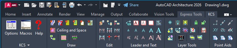
If using the Light color scheme, an alternate set of icons
will be displayed for good visibility.
Note: ACA 2010+ does not include pulldown menus. To display the KCS pulldown, use the MENUBAR command.
|
|
This toolbar may be used instead of the
standard AutoCAD Properties toolbar. It provides the Color and Linetype
controls, while eliminating the Lineweight and Plot Style controls. Saves
space if you never use those two controls.
This command creates the same kind of AEC ceiling grid object as the standard ACA commands, but much more easily. The resulting grid is automatically centered in the room in a "balanced" condition, that is with at least a half-tile at each edge. Options are provided to shift the grid by a half-tile in either direction, or pick a new alignment point at any location, or re-balance it. Note that you must be in an RCP (Reflected Ceiling Plan) display configuration for this command to work properly. One reason is that AEC ceiling grid objects do not display in a normal plan view. Another reason is that the boundary of a room cannot be found if there is a door opening; an RCP display shows the walls as continuous, which avoids this problem. If a Reflected display is not available, we suggest creating new drawings with one of the AEC templates provided, which includes a Reflected display configuration. Placement Methods include:
Options include:
Before a grid is created, you will be
prompted: The following prompt will then appear:
Add Wall (w/ Z-Lock) This command may be used in place of the standard ACA WALLADD command. This custom version allows object snapping to walls or other objects on another level without forcing the new wall to the level of the existing object. Very handy for using a previously drawn level to trace over to create another level. This command will lock the new wall at 0, or whatever your Elevation is currently set to, and ignore the Z value of the object snap.
This command adds a batt insulation pattern. It may be used with AEC walls, line walls, or anywhere else - in plans, details, or sections. Unlike other routines which use a polyline, the KCS command uses a special hatch pattern. One advantage is that it can be chopped off at an angle to allow the kind of partial hatching commonly seen in hand drafting. Another advantage is that the hatching extents can be adjusted by stretching or grip editing. Yet another advantage is that the same hatch pattern can be used in a wall style, instead of applying it separately with a command (see below). End Condition: may be set to Angled or Square, or set to prompt for which each time. You might like to use the angled end for a partial indication on long walls, but use the square condition to completely fill a shorter space. Width: Auto will work for simple two-line walls. You can choose to be prompted for complex walls. Adding
the Pattern to a Wall Style To add the pattern to a wall style, edit the wall style Display Props. In the Layer/Color/Linetype tab, turn on Hatch for the desired component. In the Hatching tab, click on the pattern name for that Hatch. In the Hatch Pattern dialog, set the pattern Type to Custom, then click the Browse button. In the Hatch Pattern Palette dialog, go to the Custom tab. Select KCS_BattInsul.pat and click OK. Back in the Hatch Pattern dialog, you must enter the pattern name KCS_BattInsul in the Custom Pattern box, then click OK. Back in the Hatch Pattern Palette dialog, set the hatch Scale to match the width of the component to be hatched, set the angle at 0, and change the orientation to Object. The drawing may get quite sluggish if there are many walls with this much hatching. There are a couple of ways to get around that. One way is to off the hatch display in that wall style until ready to plot. Or you can keep the -Patt layer frozen except for plotting. NOTE: The DTI_BattInsul.pat file is also included for backward compatibility with drawings that may have been set up using the DTI_BattInsul pattern in wall styles. For any new settings, the KCS version should be used.
Layer Change Change selected objects to another layer. Options:
Layer Copy Copy selected objects to another layer. Prompt and options are the same as Layer Change above. After objects are copied, the new objects may be selected with "Previous".
Select Layer Select all objects on picked layer. Objects may then be selected with "Previous". Layer Freeze Freeze layers of selected objects. When used inside a viewport, the layer is frozen in that viewport only. Otherwise it is frozen globally. A Nesting level
option provides three nesting levels: NOTE: Nested layer information cannot be obtained from Multi-View Blocks. The layer obtained will be its insertion layer, same as for a Nesting level of None.
Layer Off Turn off layers of selected objects. Same options as Layer Freeze except layer are turned off globally regardless of whether used inside a viewport or elsewhere.
Layer Visible Make Layers Visible - from list of non-visible layer. Layers will appear in the list if they are turned off, frozen, frozen in the current viewport, or any combination of these. A layer selected to be made visible will be turned on, thawed, and thawed in the current viewport, as required. Multiple layers may be selected.
Layer Lock Lock layers by picking objects.
Layer Unlock Lock layers by picking objects. Layer Isolate Display selected layers only (all other layers are turned off globally). Nesting level options same as Layer Freeze.
Layer Unisolate Reverse last Isolate in current drawing session.
Layer Vport Display selected layers in the current viewport only. Selected layers are frozen in all other viewports either in the current layout or all layouts, according to the Freeze level setting. Nesting level options are also available for object selection. Layer List List layer name of selected objects. When object is part of a block or xref, both the insertion layer and the nested layer are listed (with the nested layer in parentheses). Layer Set
KCS Layer Snapshot
The snapshot will capture TrueColors as well as standard colors, along with current linetypes and lineweights of layers wherever the snapshot was created.
On the other hand, you may have already applied one snapshot to your model layers, and now wish to set up one or more viewports to another snapshot. Simply uncheck Apply to Model space. There may be times when you want to apply layer properities (color, linetype, linewt) from a snapshot to the viewport(s) without altering the VP Freeze status of any layers. To do so, simply uncheck this option. Note that for best results, your Model space layers should be set as desired before applying a snap to your viewport(s). Similarly, you can control just the Freeze/Thaw status without applying the properties. These options do not apply when in Model space - all layer properties are applied to all existing layers. The Paper Space section of the dialog is disabled when in Model space, and is not present if using an AutoCAD version prior to R2008 (when VP layer properties were introduced). For older versions, a snapshot may be applied to viewports, but only the VP Freeze status is affected.
Mid of 2 Points This tool is used to locate a point midway between two specified points. It may be used whenever you are being prompted for a point. An example of this would be to locate the middle of a corridor, or any other situation where there is no object to use a midpoint osnap on.
Frac of 2 Points This tool is used to locate a point at any fractional distance between two specified points. It may be used whenever you are being prompted for a point. This button is a flyout from the Mid of 2 Points toolbar button. Set Snap AngleThis command allows you to set the snap angle by picking a line or ACA wall. You can also hit Enter to use keyboard entry or pick two points. A macro SA is also provided for this command. The macro may be used transparently during another command by preceding it with an apostrophe ('SA). A quick way to restore to 0 angle is by the SA0 macro. Get XY (specify Z)Click this to get the X,Y location of a point but input some other Z value. This is needed for the first point - after that the Hold Z filter may be used to maintain the same Z value. Z-Lock (at current elevation)Pick X,Y on screen, with Z preset to current elevation. Start command, then click this button when prompted for point. Hold X, Hold Y, Hold ZWhen specifying a point these commands may be used to retain the x, y or z value of the previous point.
KCS Leader and Text
This leader command also has the unique ability to create a series of notes on the left side of a detail using left justified text with a uniform left margin. When the second segment points to the left, the cursor changes to an I-beam, to indicate that this will be the text starting point. If a point is picked at existing text, the command will automatically osnap to its insertion point, resulting in perfect alignment. While inputting the text on screen (on the left side), additional lines of text will be created under the first, but when done they will be shifted upwards to place the last line at the point selected. (This is similar to the way AutoCAD displays right justified dtext as left justified until done.) When done, the leader tail is adjusted appropriately for the length of the last line. When drawing a leader from left to right, you may pick a point near the end of an existing leader tail to make the new leader end in alignment. Note that no AutoSnap box will appear, but an osnap will happen automatically none the less. This command can use either the current text style or a specified style. If a style is specified that does not exist, it will be created using the specified font. Text size may use the ACA Annotation Plot size (as specified in Documentation à Drawing Setup), or the current AutoCAD text size (same as standard Text commands), or as specified in the settings for this command. Automatic layer control is provided by the KCS Auto-Layer, if turned on in KCS Options. The KCS Leader uses your current AutoCAD dimension style for leaders. If you are getting a "tick" instead of an arrow, what you need to do is create a Leader sub-style and set the arrowhead to Closed Filled. You can refer to dimension style Aec_Arch_I in the "Aec arch(imperial)" template as an example. Convert to MtextThis command converts one or more lines of single-line text into an AutoCAD MTEXT object, maintaining the original text style, height and layer. The lines of text are automatically sorted according to their relative locations in the drawing. This allows multiple lines to be selected with a window or in any order. Special treatment is given to a first line ending with a colon, such as "NOTE: ". This line will remain as is and will not word-wrap with the rest of the text. This tool creates Mtext with a shadow box. The text and box are attached, so that any editing of the text will automatically update the shadow box to match. The toolbar flyout also contains a tool to attach a shadow box to existing Mtext, and another to add a freestanding shadow box anywhere in your drawing. Note that if the Mtext has the Annotative property (new for AutoCAD 2008), the shadow box will also be Annotative and will adjust to changes in scale along with the text. This does not apply to the freestanding shadow box.
Dimension Offset and Split This tool creates a copy of the selected dimension, offset in the indicated direction. The offset distance is governed by Baseline spacing (DIMDLI variable) in your dimension style settings. The two origin points of the new dimension will be the same as the original. Next you are prompted for a new origin point - the new dimension will be split in two, with a new extension originating form this point.
Dimension Split This tool splits an existing dimension into two dimensions, with a new origin point added somewhere between the two original origins, as specified.
Dimension Join This tools joins two dimension together into one.
This tool allows you to easily add a note, such as V.I.F. or CLEAR, to a dimension, as shown. The resulting text will be part of the dimension object, with the same properties as the dimension text. The same tool can also remove a previously placed note.
Dimension Dot Dimension Dot and Extension
Linetype With this tool you can change the pointer (arrow) on a dimension extension line from your normal slash or arrow to a dot. This provides the ability to implement the convention where a dot is used to indicate a dimension to the center of some object. The same tool will also restore a dot pointer to your normal pointer. Note that no additional dimension styles are created, and no changes are made to your dimension style. R2017 introduced the ability to change the linetype of extension lines. However, doing so manually is quite cumbersome, especially with stacked dimensions. Note in the sample capture the extension line with the red dotted area. Here there are extension lines from five dimensions. If they were all changed to a center linetype manually, overlapping linetypes would appear as solid in this area. This is because they are of different lengths, making them out of sync. This tool automatically handles that.
Extension Visibility Toggle This tool allows you to easily toggle a dimension extension on/off. Simply select the dim line near the extension.
This command allows you to "clone", or draw by example, almost any object already in your drawing just by picking the existing object. For all objects, it will duplicate the layer of that object. If a line is picked, it will draw a line on that layer. If text is picked, it will create text with the same style and height. If a wall is picked, it will draw a wall using the same wall style, width, height, justification, and cleanup group. And so on, for most AutoCAD and ACA objects. Align Objects
Each object picked will then be aligned to that line, according to the designated alignment point. For objects with multiple alignment points, the one closest to the point picked is used. This provides a great deal of choice in how you want objects to line up. Alignment points are at endpoints, midpoints, quadpoints, etc., depending on the type of object.
This command will replace selected block insertions with a different block. Layer, scale, rotation, and attributes of each original insertion are retained. Any number of insertions may be selected, and they need not be the same block name. The block name to use as replacement may be selected from a list of blocks in the drawing, or it may be obtained by picking an existing block.
This command will convert existing conditions to demolition. Many options are provided, with help buttons for individual options. A special Cutting Window selection option will break walls where it crosses them.
This command will label property lines (lines or polylines) with the bearing (in surveyors units) and/or distance (in decimal feet). It will give correct results whether the drawing is in foot units or inch units, by specifying which. |

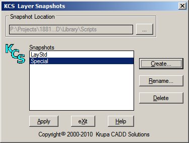
 To
Create a snapshot, you may do so
either in model space or in a viewport that has the layer settings
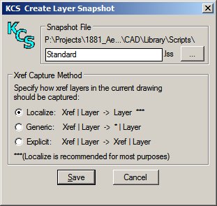
desired. Xref layers may be captured in three
different ways when creating a snapshot:
To
Create a snapshot, you may do so
either in model space or in a viewport that has the layer settings
desired. Xref layers may be captured in three
different ways when creating a snapshot: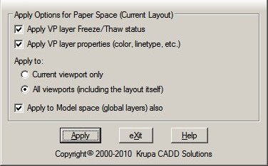 To
Apply a snapshot: when in a paper space layout, you have several
options providing maximum flexibility. With all default choices (as
shown here), the chosen snapshot will be applied to Model space layers
and layers in all viewports in the current layout, for consistent
properties throughout.
To
Apply a snapshot: when in a paper space layout, you have several
options providing maximum flexibility. With all default choices (as
shown here), the chosen snapshot will be applied to Model space layers
and layers in all viewports in the current layout, for consistent
properties throughout.  This
command creates a leader with text in a different manner than the standard
AutoCAD QLeader command. One difference is that text is created on screen,
like dtext, then (optionally) converted to mtext.
This
command creates a leader with text in a different manner than the standard
AutoCAD QLeader command. One difference is that text is created on screen,
like dtext, then (optionally) converted to mtext.  Dimension Note
 Use
this command to align text and other objects vertically or horizontally on
screen. The first object picked establishes a point of alignment (or you may
pick a point instead). The default alignment is to a vertical line passing
through this point, as indicated by a dashed screen line. Horizontal alignment
may be chosen instead.
Use
this command to align text and other objects vertically or horizontally on
screen. The first object picked establishes a point of alignment (or you may
pick a point instead). The default alignment is to a vertical line passing
through this point, as indicated by a dashed screen line. Horizontal alignment
may be chosen instead.
![]()
Options: Features that work automatically rather than by running a command.