
Version
2.20 (Released 3/19/14)
This module provides an easy way to create
steel beams (including arched or sloped beams), tags, and beam schedule, using AutoCAD
Architecture (ACA) or MEP. This module provides not only the beams, but the MVBlock
(tag),
Property Set Definition, and Schedule table style. All this is contained in one dialog, accessed by one
command - no need to access various palettes and ribbon tabs. This module may be used with or without the
KCS
Productivity Pack for AEC.
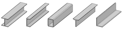
All AISC structural steel members found in the ACA Structural Member Catalog are included here.
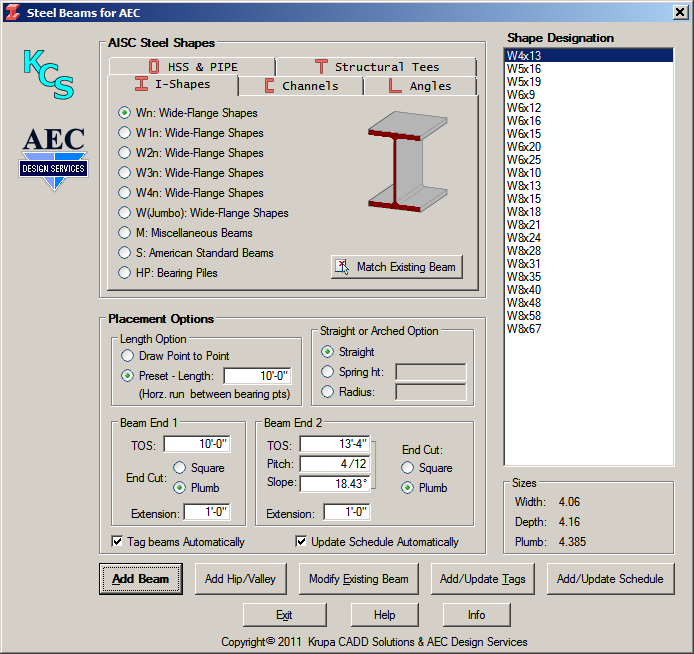
Beams created by this module, with the exception of arched beams, are exactly the same as those created by standard ACA if you were to go through all the steps involved in doing so. This module greatly simplifies the process. Select the beam you need, specify the Top Of Steel elevations, and click Add Beam to draw it. Width and Depth of the selected beam are shown for reference. Length may be or drawn on screen, as you would a line or a wall, or may be pre-specified.
Arched beams may be specified by either the Radius, if known, or the Spring Height. Arched beams are very difficult to create in standard ACA, but here it can be easily done.
This button
allows you to select a beam already placed in your drawing. The dialog
will re-display with its shape selected (with the correct tab and group
selected), and also with the placement options set to match the selected
beam.
Several options govern how a beam is placed at Add Beam:
|
Length
Options | |
|
Straight
or Arched Option | |
|
Sloped
Beams | |
End
Cuts | |
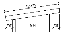 Extensions ExtensionsExtensions are measured horizontally from each bearing point, and are added outboard of these points. This applies whether you have specified a preset length or are drawing the beam from point to point on screen. |
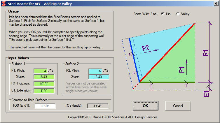
This button allows you to place a hip or valley, using the specifications currently entered. That information will be transferred to a secondary dialog and applied to Surface 1, where you can confirm or revise it. Although not absolutely necessary, we recommend that you preset the length and determine the TOS beforehand. If the two surfaces are to have a different pitch, the preset length and pitch at this point will become the horizontal run and pitch for Surface 1. If Surface 2 is to have a different pitch, its run will be adjusted to match the TOS.
Tags may be placed on beams automatically as you draw them, or they may be placed on beams already drawn by using the Add/Update Tags button. It does not matter if the beams were created by this module or previously in ACA, provided they are actually Beam Structural Members - not some other object being used to represent beams.
Tag numbers are incremented automatically for each unique beam, with respect to its physical properties and its elevation. Every time a beam is tagged all previously tagged beams are checked, and if a match is found, that number is used for the current beam. Thus different lengths of the same beam shape get different numbers, and different elevations of the same beam also get different numbers.
Previously drawn beams may be copied, moved in elevation, and stretched in length before tagging. However, if you change one of multiple beams that are already tagged, you should re-tag it to avoid having the same number for two different beams. You can update the tag by simply tagging it again.
The Tag Beams Automatically option will speed up your work when placing new beams and is recommended, unless you want more control over which beams get what numbers.
Note that the
beams, tags, and schedule must reside in the same drawing.
The Steel Beam Schedule is an ACA Schedule Table Style created specially for this module. Text styles used are the same as used by ACA in other schedules and may be easily modified by the STYLE command according to your preferences.
To create a schedule, once you have placed and
tagged beams, click the Add/Update Schedule button and place it as
desired. If you later add more beams, they can be added to the schedule in three
ways. If the Update Schedule Automatically option in turned on,
the beam will be added to the schedule as soon as it is tagged, whether
tagging it automatically as drawn or afterwards. This option is
recommended, along with Tag Beams Automatically,
unless perhaps you have a very large number of beams and
experience a delay for each addition. If this is the case, you can turn
this option off, and simply click the Add/Update Schedule
button to update the schedule. (Note that Update Schedule Automatically
is disabled if Tag Beams Automatically
is turned off.)
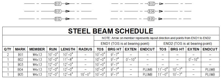
Bearing Height is a result of the Top Of Steel
minus the beam depth, and then rounded down to the nearest inch. This provides
space for shimming, per standard practice. If both ends of the beam are at the
same height, TOS and BRG HT for END2 will be blank, for easier reading.
New for v2.10: A direction arrow is also placed near the tag for all beams. This is to provide orientation in the field for any beams having precut openings or any other non-symmetrical features.
Note that for arched beams, the radius is given
here regardless of whether it was specified by Radius or by Spring Ht, as needed
for fabricating the beam. Note also that the length given is the arc length of
the beam.
This button will allow you to modify the properties of an one or more
existing beams to match the style, TOS, and arch properties (if any), as
currently set in the dialog. The beam will retain it's endpoints, except
as modified by the current TOS setting. Any preset length in the dialog
will be ignored.
![]() The
ACA functionality used by this module to create an arched beam displays a dialog
box
that does not need any input in this context, but has no means of being
suppressed. To avoid confusion and extra
clicks, we provide an external utility that dismisses this dialog
automatically. You will see it on screen briefly before it is dismissed - this is normal. The name of this utility is Steel Beams
Dialog Control, and you will see it in your Windows taskbar. It is
automatically activated by this module whenever needed, and may be
exited whenever you wish.
The
ACA functionality used by this module to create an arched beam displays a dialog
box
that does not need any input in this context, but has no means of being
suppressed. To avoid confusion and extra
clicks, we provide an external utility that dismisses this dialog
automatically. You will see it on screen briefly before it is dismissed - this is normal. The name of this utility is Steel Beams
Dialog Control, and you will see it in your Windows taskbar. It is
automatically activated by this module whenever needed, and may be
exited whenever you wish.
For any problems, critiques, or kudos, please contact kcs@krupacadd.com or aecds@AECDesignSVCS.com. We'd like to hear from you.
![]()
2.20 - Revised for R2014 and ODCL 8.0.0.4, schedule improved, end bubbles eliminated.
2.10 - Revised for R2013 and ODCL 7.0.0.4, direction arrows added
2.06 - Misc bugfix
2.05 - Misc bugfix
2.04 - Misc bugfix
2.03 - Misc bugfix
2.02 - Misc bugfix
2.01 - Revised for MEP compatibility
2.00 - Many features added, including sloped beams, arched beams, and all AISC steel shapes
1.00 - Initial release