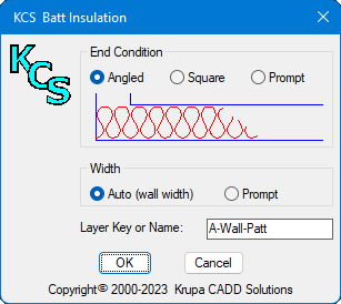
This command adds a batt insulation pattern. It may be used with AEC walls, line walls, or anywhere else - in plans, details, or sections. Unlike other routines which use a polyline, the KCS command uses a special hatch pattern. One advantage is that it can be chopped off at an angle to allow the kind of partial hatching commonly seen in hand drafting. Another advantage is that the hatching extents can be adjusted by stretching or grip editing. End Condition: may be set to Angled or Square, or set to prompt for which each time. You might like to use the angled end for a partial indication on long walls, but use the square condition to completely fill a shorter space. Width: Auto will work for simple two-line walls. You can choose to be prompted for complex walls. This command will draw a line with a specified angle starting at the tangent point of an arc or circle. Once you specify the angle and select the arc, a line will start at that tangent point, with Ortho turned on and set to that angle. Note that you can continue to draw line segments at that angle, until you end or cancel the command. The original angle and Ortho status are both restored at that time. This command is available as a button, and as a macro.
Copy selected objects to another layer.
Prompt and options are the same as Layer Change above.
Select all objects on picked layer. Objects may then be selected with "Previous".
Freeze layers of selected objects. When used inside a viewport, the layer is frozen in that viewport only. Otherwise it is frozen globally. A Nesting level
option provides three nesting levels:
Turn off layers of selected objects. Same options as Layer Freeze except layer are turned off globally regardless of whether used inside a viewport or elsewhere.
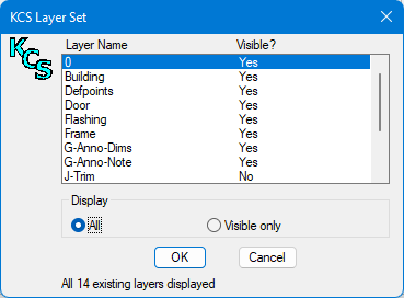
Make Layers Visible - from list of non-visible layer. Layers will appear in the list if they are turned off, frozen, frozen in the current viewport, or any combination of these. A layer selected to be made visible will be turned on, thawed, and thawed in the current viewport, as required. Multiple layers may be selected.
Lock layers by picking objects. Lock layers by picking objects.
Display selected layers only (all other
layers are turned off globally). Reverse last Isolate in current drawing session. Display selected layers in the current viewport only. Selected layers are frozen in all other viewports either in the current layout or all layouts, according to the Freeze level setting. Nesting level options are also available for object selection. List layer name of selected objects.
The snapshot will capture TrueColors as well as standard colors, along with current linetypes and lineweights of layers wherever the snapshot was created.
On the other hand, you may have already applied one snapshot to your model layers, and now wish to set up one or more viewports to another snapshot. Simply uncheck Apply to Model space. There may be times when you want to apply layer properities (color, linetype, linewt) from a snapshot to the viewport(s) without altering the VP Freeze status of any layers. To do so, simply uncheck this option. Note that for best results, your Model space layers should be set as desired before applying a snap to your viewport(s). Similarly, you can control just the Freeze/Thaw status without applying the properties. These options do not apply when in Model space - all layer properties are applied to all existing layers. The Paper Space section of the dialog is disabled when in Model space, and is not present if using an AutoCAD version prior to R2008 (when VP layer properties were introduced). For older versions, a snapshot may be applied to vieports, but only the VP Freeze status is affected.
Standard AutoCAD command, included for convenience. Restore Layer states to prior to last
Layer command.
This tool is used to locate a point a specified distance and angle from a base point. Unlike standard AutoCAD tracking and From tools, this Ref Point tool will keep prompting for another point until you press Enter. This allows going in more than one direction to arrive at the desired location.
This tool is used to locate a point midway between two specified points. It may be used whenever you are being prompted for a point. An example of this would be to locate the middle of a corridor, or any other situation where there is no object to use a midpoint osnap on.
This tool is used to locate a point at any fractional distance between two specified points. It may be used whenever you are being prompted for a point. This button is a flyout from the Mid of 2 Points toolbar button.
|
|||||||||||||||||||||||||||||||||||||||||||||||||||||||||||||||||||||||||||||||||||||||||||||||||||||||||||||||||||||||||||||||||||||||||||||||||||||||||||||||||||||||||||||||||||||||||||


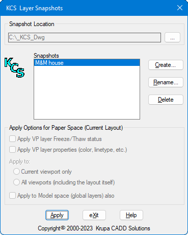
 To
Create a snapshot, you may do so either in model space or in a
viewport that has the layer settings desired. Xref layers may be
captured in three different ways when creating a snapshot:
To
Create a snapshot, you may do so either in model space or in a
viewport that has the layer settings desired. Xref layers may be
captured in three different ways when creating a snapshot: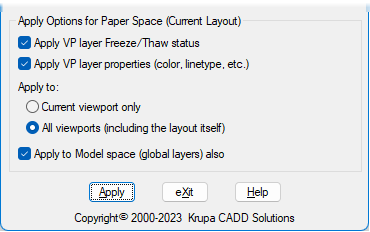 To
Apply a Snapshot: when in a paper space layout, you have several
options providing maximum flexibility. With all default choices (as
shown here), the chosen snapshot will be applied to Model space layers
and layers in all viewports in the current layout, for consistent
properties throughout.
To
Apply a Snapshot: when in a paper space layout, you have several
options providing maximum flexibility. With all default choices (as
shown here), the chosen snapshot will be applied to Model space layers
and layers in all viewports in the current layout, for consistent
properties throughout.
Get XY (specify Z)
Click this to get the X,Y location of a point but input some other Z value. This is needed for the first point - after that the Hold Z filter may be used to maintain the same Z value.
Z-Lock (at current elevation)
Pick X,Y on screen, with Z preset to current elevation. Start command, then click this button when prompted for point.
|
|
Hold X, Hold Y, Hold Z
When specifying a point these commands may be used to retain the x, y or z value of the previous point.
KCS Leader and Text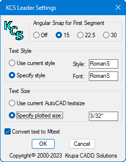
This command creates a leader with text in a different manner than the standard AutoCAD QLeader command. One difference is that text is created on screen, like dtext, then (optionally) converted to mtext.
This leader command also has the unique ability to create a series of notes on the left side of a detail using left justified text with a uniform left margin. When the second segment points to the left, the cursor changes to an I-beam, to indicate that this will be the text starting point. If a point is picked at existing text, the command will automatically osnap to its insertion point, resulting in perfect alignment.
While inputting the text on screen (on the left side), additional lines of text will be created under the first, but when done they will be shifted upwards to place the last line at the point selected. (This is similar to the way AutoCAD displays right justified dtext as left justified until done.) When done, the leader tail is adjusted appropriately for the length of the last line.
When drawing a leader from left to right, you may pick a point near the end of an existing leader tail to make the new leader end in alignment. Note that no AutoSnap box will appear, but an osnap will happen automatically none the less.
 This command can use either the current text
style or a specified style. If a style is specified that does not exist,
it will be created using the specified font. Text size may use the the current AutoCAD text size (same as standard
Text commands), or as specified in the settings for this command.
Automatic layer control is provided by the KCS Auto-Layer,
if turned on in KCS Options.
This command can use either the current text
style or a specified style. If a style is specified that does not exist,
it will be created using the specified font. Text size may use the the current AutoCAD text size (same as standard
Text commands), or as specified in the settings for this command.
Automatic layer control is provided by the KCS Auto-Layer,
if turned on in KCS Options.
The KCS Leader uses your current AutoCAD dimension style for leaders. To change the arrow head, create a Leader dimension sub-style and choose the arrowhead desired.
Convert to Mtext
This command converts one or more lines of single-line text into an AutoCAD MTEXT object, maintaining the original text style, height and layer. The lines of text are automatically sorted according to their relative locations in the drawing. This allows multiple lines to be selected with a window or in any order.
Special treatment is given to a first line ending with a colon, such as "NOTE: ". This line will remain as is and will not word-wrap with the rest of the text.
| |
|
|
This tool creates Mtext with a shadow box. The text and box are attached, so that any editing of the text will automatically update the shadow box to match. The toolbar flyout also contains a tool to attach a shadow box to existing Mtext, and another to add a freestanding shadow box anywhere in your drawing.
Dimension Offset and Split
This tool creates a copy of the selected dimension, offset in the indicated direction. The offset distance is governed by Baseline spacing (DIMDLI variable) in your dimension style settings. The two origin points of the new dimension will be the same as the original. Next you are prompted for a new origin point - the new dimension will be split in two, with a new extension originating form this point.
Dimension Split
This tool splits an existing dimension into two dimensions, with a new origin point added somewhere between the two original origins, as specified.
Dimension Join
This tools joins two dimension together into one.
 Dimension Note
This tool allows you to easily add a note, such as V.I.F. or CLEAR, to a dimension, as shown. The resulting text will be part of the dimension object, with the same properties as the dimension text. The same tool can also remove a previously placed note.
Dimension Dot and Extension
Linetype
With this tool you can change the pointer (arrow) on a dimension extension line from your normal slash or arrow to a dot. This provides the ability to implement the convention where a dot is used to indicate a dimension to the center of some object. The same tool will also restore a dot pointer to your normal pointer. Note that no additional dimension styles are created, and no changes are made to your dimension style.
R2017 introduced the ability to change the linetype of extension lines. However, doing so manually is quite cumbersome, especially with stacked dimensions. Note in the sample capture the extension line with the red dotted area. Here there are extension lines from five dimensions. If they were all changed to a center linetype manually, overlapping linetypes would appear as solid in this area. This is because they are of different lengths, making them out of sync. This tool automatically handles that.
Extension Visibility Toggle
This tool allows you to easily toggle a dimension extension on/off. Simply select the dim line near the extension.
Mechanical
Dimensioning Tools
![]()
These commands were created for
mechanical, machine, and tool drawings, where different dimensions
require different formats. For instance, a three place dimension may
denote a tolerance (without being shown in the dimension) of .015, while
a two place dimension denotes a tolerance of .03. Along with this, some
dimensions may carry an explicit tolerance, which may vary for each one
both in value(s) and format. Doing this in AutoCAD is quite awkward, but
these tools make it easy. They all use your current dimension style,
applying the appropriate overrides to selected dimension objects.
Spot_ID
This command allows you to place spot coordinates, with respect to a specified base point. This can be extremely useful for supplying coordinates for use by CNC machine programming. The command offers two modes, Surface and Diameter. In Surface mode, the coordinates are in X,Y format. In Diameter mode, the format is X,Z, where the X value is actually twice the drawing Y value (converting the radius to a diameter), and the Z axis value given is the drawing X value (for CNC lathe input).
For both modes, the text style and size match that of your current dimension style. The number of decimal places is determined by your current LUPREC (linear units precision) value, which may be set either directly by the LUPREC command, or by the UNITS command.
Add Diameter Symbol
This command adds a diameter symbol to a dimension that is placed on a side or edge view of a circular object. It can also be used for text.
Dimension Tolerance
This command allows you to easily add an explicit tolerance to any dimension. All four formats available in AutoCAD are provided by this command, as shown in the examples. A "None" option is also provided for removing a tolerance. Note that the default tolerance precision and text size are controlled by the Tolerance settings for your current dimension style.
![]() Reference
Dimension
Reference
Dimension
This commands encloses a dimension in parentheses, to denote it as a reference dimension. It can also be used on text.
| |
| - |
|
Dimension Precision
These commands allow you to control the precision of each dimension independently from its dimension style. For example, you might set up your dimension style for three decimal places to serve the majority of your dimensions. You can then use these commands to change the number of decimal places for any of those dimensions, as required.
Draw
By Example (Clone)
This command allows you to "clone", or draw by example, almost any object already in your drawing just by picking the existing object. For all objects, it will duplicate the layer of that object. If a line is picked, it will draw a line on that layer. If text is picked, it will create text with the same style and height. And so on, for most AutoCAD objects.
Align Objects
 Use
this command to align text and other objects vertically or horizontally
on screen. The first object picked establishes a point of alignment (or
you may pick a point instead). The default alignment is to a vertical
line passing through this point, as indicated by a dashed screen line.
Horizontal alignment may be chosen instead.
Use
this command to align text and other objects vertically or horizontally
on screen. The first object picked establishes a point of alignment (or
you may pick a point instead). The default alignment is to a vertical
line passing through this point, as indicated by a dashed screen line.
Horizontal alignment may be chosen instead.
Each object picked will then be aligned to that line, according to the designated alignment point. For objects with multiple alignment points, the one closest to the point picked is used. This provides a great deal of choice in how you want objects to line up. Alignment points are at endpoints, midpoints, quadpoints, etc., depending on the type of object.
This command will replace selected block insertions with a different block. Layer, scale, rotation, and attributes of each original insertion are retained. Any number of insertions may be selected, and they need not be the same block name. The block name to use as replacement may be selected from a list of blocks in the drawing, or it may be obtained by picking an existing block.
Options: Features that work automatically rather than by running a command.